This article Explain how to wire cat 5 cat 6 ethernet pinout rj45 wiring diagram with Cat 6 color code , Networks have become one of the essence in computer world and for better Internet facilities ti gets extremely important to built a good, secured and reliable network. When ti comes to built your own reliable network most of the users don’t know how to wire Ethernet cables to built up a good network for their LAN connections. In order to make a secure wiring over the LAN with Ethernet wires you will need the following: –
- Some Instructions to make Cat6 Patch Cable:
- Ethernet cables: – bulk CAT 5, 5e,cat 6 , 6a or cat 7 or higher Ethernet cables as per your requirement.
- Wire cutters: – to cut and strip the wires.
- For Patch cables: – 8P8C Modular Connector Plugs (RJ45) and Modular Connector Crimper
- For Fixing Wires: – 8P8C Modular Connector Jacks and 110 Punch Down tools
- Wire striper and Cable Tester also required.
While wiring Ethernet cables most important part is the proper linking of wires with the respective codes and connectors. Inside the cable there are 8 color coded wires twisted in the 4 pairs of wires and each pair has a common color theme. One of the wire in the pair is of solid color while other one is a primarily white wire with a colored stripe making it easy how to wire Ethernet cables.
Internal Cable Structure and Color Coding of the wire is
- Orange / Orange White
- Green / Green–White
- Blue / Blue–White
- Brown / Brown–White
It is very important to connect the wires with the respective color sequence and codes while using the RJ45- position modular connector. You need the RJ45 connectors to connect the wires due to Physical resemblance.
There are mainly two types of Ethernet Cable Pin Outs. First one is a Straight through cable which is used to connect to a hub or switch and second one is a Crossover cable which is used to operate in a peer to peer fashion without using a hub/switch.
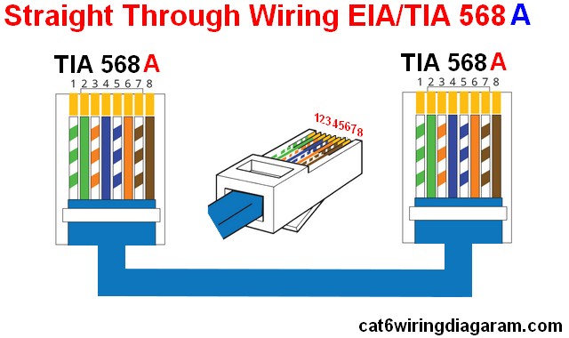
– Standard straight-Through Wiring Diagram (both ends are the same)
- Straight-Through EIA/TIA 568a
- Straight-Through EIA/TIA 568b
– Standard Crossover Cable wiring diagram :
How to crimp Ethernet Rj45
It is simple to wire Ethernet cables with the help of following steps: –
- Remove the cable sheath for about 2 inches.
- Now untwist the cable wires but don’t untwist them beyond what you have exposed.
- Adjust the colored wires according to the above diagrams.
- Trim all the aligned wires to the same length of about 1/2” to 3/4” should be left exposed form the sheath.
- Now insert the wires into the RJ45 end and make sure that each wire is fully inserted to the front of the RJ45 end and in the correct order.
- Verify the ended up and alignment of the wire that it remain the right order and that the wires extend to the front of the RJ45 end and make good contact with the metal contacts in the RJ45 end.
- Now Crimp the RJ45 end with the Crimper tool.
- Cut the cable to the length and make sure it is more than long enough to the need.
- Now you need to repeat the same steps for the RJ45 end and connectors.
- Use a Ethernet cable tester to verify the proper connectivity of the wires.
If your Ethernet cable does not work look, properly to each and every end of the wires and try to figure out the problem of the misplaced wire and connect them in the right order for the proper functioning of the Ethernet wiring and secured LAN system
Are You Interested in article :
- Crossover color code
- Cat 6 Gegabit wiring
- Straight cable wiring diagram


